SPF5189 LNA measurements
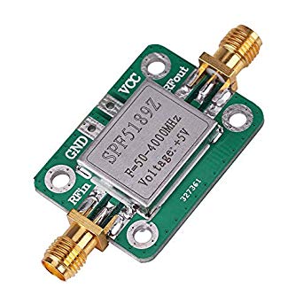
If you want to improve your receiving station performances, you could consider to add an LNA near your antenna. One of the cheapeset LNA available on the market is SPF5189. It's available already mounted on a PCB, shielded and connectorized, as in the figure below.
I bought one board for few euros on ebay. It arrived in a pair of weeks, then I measured it on a Vector Network Analyzer, in order to compare the real gain with the datasheet.
Once the LNA has been powered at 5V, the current absorption is 90mA, perfectly aligned with the datasheet range.
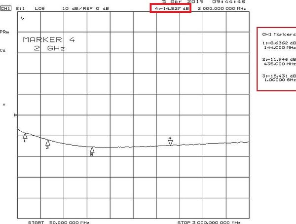
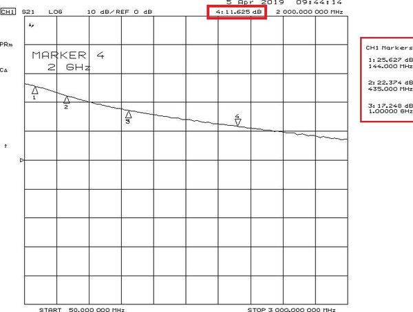
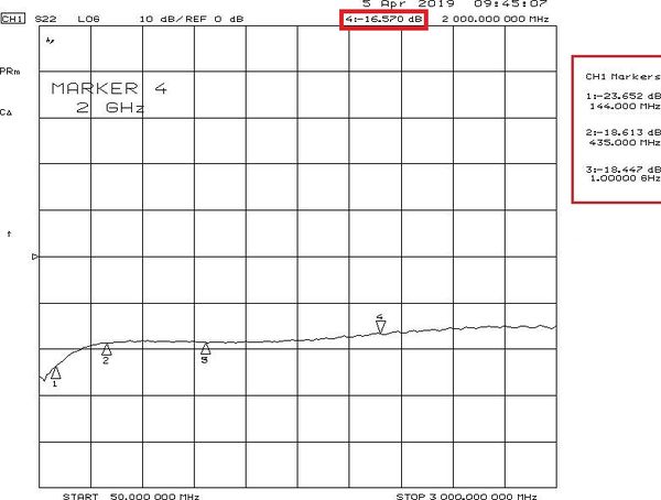
Here below, the S21, S11 and S22 plots are reported between 50MHz and 3GHz (the LNA reaches 4GHz but the VNA not).
I placed these 4 markers: 144MHz, 435MHz, 1GHz, 2GHz .
When I downloaded the datahseet, I saw that the SPF5189Z has two possible configurations:
- Optimized matching at 900MHz - Optimized matching at 1900MHz
From ebay description and board P/N, it’s not possible to understand the frequency optimization.
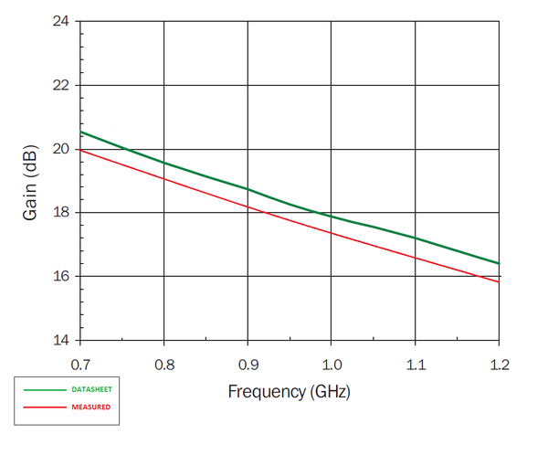
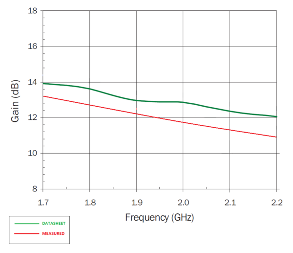
Here below, I reported a comparison the datasheet (green line) and the measurement (red line) data, for both configurations. The frequency range of the datasheet is smaller than my measurements, sto the comparison is only on the datasheet frequencies and not wide-band.
The gain seems to be 1dB less than the datasheet on both configurations, while the input matching shows better results on 900MHz range.
At the end, the LNA is quite wide-band and is a compromise between the 900MHz and 1900MHz configurations.
