SatNOGS Rotator v3
| SatNOGS Rotator v3 | |
|---|---|
| Rotator Information | |
| Type: | Az/El |
| Cost: | ~220 USD |
| Release Information | |
| Status: | Beta |
| Latest Release: | Torx Flathead (v3.0.1) |
| Repository: | [1] |
| Documentation: | [[2] [3]] |

Intro
v3 marks a major re-haul of the SatNOGS Rotator design, with learnings from v2 applied. You can see a lot of the thinking and background research that was conducted prior to v3 development in this thread. Also in this wiki page you can also find a "How to build the rotator", mechanical analysis and all documentation about the SatNOGS rotator.
Also in this list is presented different rotators, either commercial or DIY builds.
Specifications
| SatNOGS v3 Rotator | ||
| Plastic Parts | 15 | |
| Non Printed Parts | 38 | |
| Cost | ~ $220 | |
| Controller Electronics | SatNOGS Rotator Controller | |
| Type | AZ/EL (possible X/Y) | |
| Motors | 2x NEMA 17 Stepper or 2x DC Motors | |
| Frame Material | Aluminum T-slot 20x20 | |
| Speed (deg/sec) | 7 | |
| Torque (Nm) | ?, ~30 | |
| Brake Torque (Nm) | ? | |
| Dimensions (mm) | 280x140x140 (AZ/EL) | |
| Weight (kg) | ~5 |
Brake Torque
The greatest force the tracker needs to withstand is the force created by strong wind. The worst case is when one antenna is elevated at 90 degs, facing the direction of the wind. We based our calculations on an article found online after comparing it to others. We “translated” the second table in metric (because we don’t understand imperial and because we needed same units system in our calculations)
| Method | Wind Zone(km/h) | Height (m) | Pressure(N/m^2) |
|---|---|---|---|
| EIA-222-C | 160 | N/A | 1280 |
| EIA-222-F | 128 | 14 | 1260 |
| EIA-222-F | 128 | 21 | 1390 |
| EIA-222-F | 128 | 30 | 1500 |
| UBC'97 | 128 | 14 | 1290 |
| UBC'97 | 128 | 21 | 1160 |
| UBC'97 | 128 | 21 | 1390 |
| UBC'97 | 128 | 30 | 1260 |
| UBC'97 | 128 | 42 | 990 |
| UBC'97 | 128 | 42 | 1360 |
| Generic Formula | 150 | N/A | 1270 |
and we applied the worst case model (EIA-222-F) in 3 different antennas: in the biggest one of our designs, and in two others, for which we obtained data from yaesu G800 rotator manual at page 3. We assumed that antennas are mounted in 1m away from the azimuth axis. For our antenna with 2m length (actual, not wavelength), made by 2cm square tube, the generated torque was ≈600Kg*cm. For the 144MHz 10-elements Yagi from the article is ≈6000Kg*cm and for the third 430MHz, 12-elements Yagi is ≈1800Kg*cm
Moment of inertia
Now for the moment of inertia: (for all installation methods we assumed that antennas are counterbalanced in the elevation axis) the worst case scenario here is to use two 3kg (our designs are less than 1kg) back mounted yagis with 3kg counterbalances both mounted in 0.75m away from azimuth axis. The torque you need in order to accelerate this system from ω=0deg/s angular velocity to ω=5deg/s (the math about angular velocity is below) in one second is about 60kg*cm.
Note: we suppose that the mass of antennas is near to the altitude axis, so the torque of this axis that is needed to accelerate is approximately 0.
- M1: torque of Azimuth axis
- L: length of center of mass of antennas from azimuth axis (0.75m)
- m: mass of antennas and of counterweight (3kg + 3kg = 6kg)
- I: moment inertia
- a: angular acceleration of azimuth axis 5deg/s^2
- I = I1 + I2 = m*L^2 + m*L^2 = 2*m*L^2 = 6.75 kg*m^2
- M1 = I*a = 6.75kgm^2 * 0.087rad/s^2 = 0.58 Nm = 5.8 kgm = 58 kgcm
Angular velocity
(How well do you remember trigonometry?)For the angular velocity max needed in altitude axis the things are straightforward. The closer is the satellite the larger the velocity. According to the wikipedia article about LEO, the lowest height limit is 160 km and the speed unit to orbit earth in this altitude is 7,8 km/s. As a result, maximum velocity in ALT axis is 2,8 deg/s. In ALT AZ rotator design there is a well known limitation: the closer something passes near zenith the biggest gets the velocity of the AZ axis. Therefore, we have analyzed this problem to figure out the optimal velocity and how high we are allowed to track a target in relation to AZ velocity. The picture below illustrates a ground station B which tracks a satellite Γ in X degrees altitude. The satellite velocity at this point is vertical to the screen (page) plane.

The equations that lead to maximum altitude at which we can track in relation to AZ angular velocity are
- ω : angular velocity of AZ DOF in rad/s
- H = ΑΕ + ΕΓ : Minimum Height of LEO, 160 km
- R = ΑΕ : Radius of Earth, 6500 km
- u : linear velocity of satellite that rotates in 160km height is 7.8 km/s
- ΒΔ = u / ω : ΒΔ in km
- α = atan(ΒΔ / R)
- δ = π - α
- γ = asin( sqrt(R^2+ΒΔ^2) * sin(δ) / (H+R) )
- ά = π - δ - γ
- ΓΔ = (H+R) * sin(ά) / sin(δ)
- χ = atan(ΓΔ / ΒΔ)
Below you can see the plot of the equations mentioned above, where horizontal axis represents angular velocity (ω) in deg/s and vertical axis shows the max track altitude (χ) for lower bound of LEO.

After studying this diagram, we came up to the conclusion that an angular velocity of 5 deg/s is adequate. For this decision, we took into consideration the main lobe of antenna (Δ3db) which in most situations is about 20 deg.
General Specifications
Together with the above mentioned specifications, we would also like for the 3rd version of SatNOGS rotator to be:
- inexpensive (less than €300, if possible)
- lightweight and portable (~6Kg, size:~300x~150x~150mm)
- rigid and durable
- easy to build and fix (try to use easily available materials)
- weatherproof
- electromagnetically shielded, so that noise in reception is reduced
- accurate (<1deg, backslash reduction and use of encoders at the axis)
Sourcing
3d Printing at a Fab Lab or your local hackerspace: If you don't have your own 3d printer, then a local Fab Lab or hackerspace may be able to do it for you. Fab Labs and hackerspaces are places that have invested in the machinery and you can take the designs to them. Generally they need .stl files to import into the software that runs the machines, but this should be discussed with the Fab Lab or hackerspace. You then pay for the material, time or a combination of the two for each of the parts or any other agreement in place.
Most people building the rotator have had success builds with simple ABS material for the 3D printing parts.
T Slot - If you don't want to cut the pieces yourself, then you may be able to find a supplier that will do this for you. (Here's one in the United Kingdom.)
Hidden corner connectors - AliExpress gave the cheapest supplier
A good US source is MISUMI-USA; they will also cut to length. MISUMI has several other global locations [4].
Beware, the 20-series T-slot from 80/20 Inc. in the US has slots that are only 5.2mm wide. The hidden corner connectors from e.g. AliExpress will not fit.
Stepper Motors - eBay
Belts - eBay
Fixings / Pipe - eBay
Vendors Table
Like the RepRap Buyers' Guide wiki, feel free to populate the table.
| Vendor | Location | Parts | Notes |
|---|---|---|---|
| pololu | USA, Worldwide | Motors, electronics | - |
| mouser | Worldwide | Motors, electronics | - |
| ebay | Worldwide | Motors, electronics, Fasteners, T-Slots, pulleys, Tubes | - |
| aliexpress | Worldwide | Motors, electronics, Fasteners, T-Slots, pulleys, Tubes | - |
| grobotronics | GR, EU | Motors, electronics, Fasteners, T-Slots, pulleys | - |
| motedis | DE, EU | T-Slots, Tubes | - |
| Misumi | Worldwide | T-Slots, Tubes, Fasteners, Pulleys | - |
| omc-stepperonline | Worldwide | Stepper motors | - |
| fastenal | USA | Fasteners | - |
| mcmaster | USA | Fasteners | - |
| rs | Worldwide | Electronics, fasteners, motors | - |
| 80/20 | USA | T-Slots | - |
| pcbway | CN | PCB fabrication | - |
| servocity | USA | Motors, T-slots, fasteners | Most of parts are not metric |
Build Sequence
Tools & Consumables
Here are presented tools and consumables about part fabrication, port-processing and assembly process. Most of the tools are available in every hackerspace, makerspaces, FabLabs etc.
| Tool/Consumable | Description |
|---|---|
| Drill bits | 2mm for aluminum, 3mm, 4mm and 5mm for plastic |
| Drill driver | For aluminum tube drill hole, 3D printed part |
| Sandpaper | 80(dry), 120(dry), 240(dry) and 1000(wet) grit |
| Acetone | For acetone vapor bath |
| Hacksaw | For aluminum Tube |
| Square File | For worm axis, for use on steel |
| Precision Knife | For general use, especially in 3d-Printed parts |
| Caliper | Measuring Range 0-150mm |
| Combination Wrenches | 5.5mm, 7mm and 8mm |
| Thread-locker | Like Loctite 271 |
| Cyano acrylic glue | Like Loctite 401 |
| Screw driver | Number 1 Phillips |
| Heat Gun | For Heat-shrinkables or use a lighter |
| Ball-End L-Keys | Hex 1.5mm, 2mm, 2.5mm, and 3mm |
| Soldering iron and consumables | For cables |
| Wire Cutter | For cables |
| Long-Nose Plier | General purpose |
Parts
Make sure you have all parts, according to BOM.
Most of the parts could be fabricated by a FDM 3D-printer. Some parts have only 2D geometry so could be fabricated by a laser cutter. Other parts have modifications of common(hardware) parts like threaded rods or aluminum pipes. Also you could find a lot of guides for post processing for FDM printed parts.
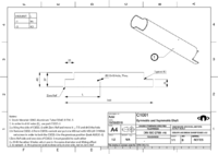
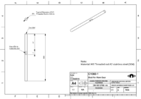
C1001, Aluminum Tube 6063 OD40mm TH1.5mm L240mm, 2 variants -1 and -3
C1010-3, FDM-3Dprinted, Material: ABS, Layer height: 0.4 mm, Perimeters: 2, Top/bottom solid layers: 3, Fill density: 20%, Fill pattern: Honeycomb, Fan speed: [35, 100], No support material
C1011-3, laser cut in 3mm Acrylic Sheet or in FDM-3Dprinter with same fabrication parameters as C1010-3
C1020-1, FDM-3Dprinted, Material: ABS, Layer height: 0.4 mm, Perimeters: 2, Top/bottom solid layers: 3, Fill density: 20%, Fill pattern: Honeycomb, Fan speed: [35, 100], No support material, Smoothing the part with acetone vapor bath
C1021-1, FDM-3Dprinted, Material: ABS, Layer height: 0.4 mm, Perimeters: 2, Top/bottom solid layers: 3, Fill density: 20%, Fill pattern: Honeycomb, Fan speed: [35, 100], No support material, Smoothing the part with acetone vapor bath, Imperial variant, tool that helps to build imperial part
C1022-3, laser cut in 3mm Acrylic Sheet or in FDM-3Dprinter with same fabrication parameters as C1010-3
C1030-1, FDM-3Dprinted, Material: ABS, Layer height: 0.4 mm, Perimeters: 2, Top/bottom solid layers: 3, Fill density: 20%, Fill pattern: Honeycomb, Fan speed: [35, 100], No support material
C1040-1, FDM-3Dprinted, Material: ABS, Layer height: 0.4 mm, Perimeters: 2, Top/bottom solid layers: 3, Fill density: 20%, Fill pattern: Honeycomb, Fan speed: [35, 100], No support material, Imperial variant, tool that helps to build imperial part
C1041-1, FDM-3Dprinted, Material: ABS, Layer height: 0.4 mm, Perimeters: 2, Top/bottom solid layers: 3, Fill density: 20%, Fill pattern: Honeycomb, Fan speed: [35, 100], No support material, Imperial variant, tool that helps to build imperial part
C1042-1, laser cut in 3mm Acrylic Sheet or in FDM-3Dprinter with same fabrication parameters as C1010-3
C1043-1, FDM-3Dprinted, Material: ABS, Layer height: 0.4 mm, Perimeters: 2, Top/bottom solid layers: 3, Fill density: 20%, Fill pattern: Honeycomb, Fan speed: [35, 100], Support material, Brim Width: 2 mm
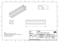
C1050, Aluminum Profile 20x20 B-type slot 6, 2 variants -1 and -5
C1060-1, M5 Threaded rod A2 stainless steel(304)
C1061, 2 variants -5 and -6, FDM-3Dprinted, Material: ABS, Layer height: 0.4 mm, Perimeters: 2, Top/bottom solid layers: 3, Fill density: 20%, Fill pattern: Honeycomb, Fan speed: [35, 100], No support material
C1062-1, It is recommended to build in laser sintering like Shapeways with White Versatile Plastic (cost ~10€) or like C1030-1 and Smoothing the part with acetone vapor bath
C1070-1, FDM-3Dprinted, Material: ABS, Layer height: 0.4 mm, Perimeters: 2, Top/bottom solid layers: 3, Fill density: 20%, Fill pattern: Honeycomb, Fan speed: [35, 100], No support material
C1071-1, FDM-3Dprinted, Material: ABS, Layer height: 0.4 mm, Perimeters: 2, Top/bottom solid layers: 3, Fill density: 20%, Fill pattern: Honeycomb, Fan speed: [35, 100], No support material
C1072-1, FDM-3Dprinted, Material: ABS, Layer height: 0.4 mm, Perimeters: 2, Top/bottom solid layers: 3, Fill density: 20%, Fill pattern: Honeycomb, Fan speed: [35, 100], No support material

C1083-1, FDM-3Dprinted, Material: ABS, Layer height: 0.4 mm, Perimeters: 2, Top/bottom solid layers: 3, Fill density: 20%, Fill pattern: Honeycomb, Fan speed: [35, 100], No support material
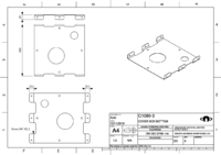
C1080-3, Cover Box bottom part, galvanized steel sheet, thickness 0.5mm
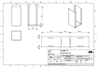
C1081-3, Cover Box top part, galvanized steel sheet, thickness 0.5mm
C1082-5, Cover Box side part, galvanized steel sheet, thickness 0.5mm
C1084-1, FDM-3Dprinted, Material: ABS, Layer height: 0.4 mm, Perimeters: 2, Top/bottom solid layers: 3, Fill density: 20%, Fill pattern: Honeycomb, Fan speed: [35, 100], No support material


Assembly
Follow the instructions for mechanical assembly and also you can watch timelapse Also, exploded views and instructions are present here.
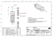
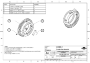
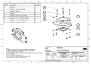
Step 1, Prepare the assembly of worm gear
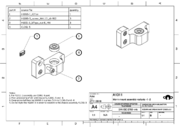
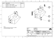
Step 2, Prepare the assembly of worm gear mount, 2 variants -1 and -2 (mirror)
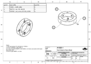
Step 3, Prepare the assembly of shaft collar for worm wheel
Step 4, Prepare the encoder gear
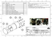
Step 5, Prepare the Motor mount
Step 6, In case of DC motor configuration
Step 7, Bearing side without encoder and end-stop mounts
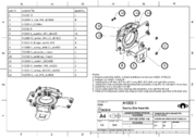
Step 8, Bearing side with encoder and end-stop mounts
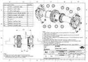
Step 9, Prepare symmetric and asymmetric axis, 2 variants -1 and -3
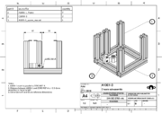
Step 10, Frame with worm gear mount and A1001-1 assembly
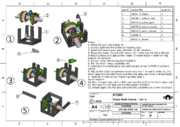
Step 11, Rotator module 2 Variants -1 and -3, symmetric and asymetric
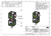
Step 12, Final step of Antenna Rotator


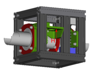
Rotator Controller
Once mechanical assembly is ready, construct the SatNOGS Rotator Controller. Also construct the rotary encoders for DC motor set up.
Cover Box - Cabling
Prepare the cover box and install it to antenna rotator with rotator controller and cables.
Testing
You are ready! Proceed with testing.
Heading Calibration
The heading calibration is a manual process:
- Power the rotator, it starts moving in order to find the home position, to find the end-stops
- Remove the power from the rotator, the rotator is in home position
- Install the rotator to vertical axis by using U-Bolt clamps
- The azimuth axis it must be heading to the North, this is achieved by using a compass (e.g. from smart phone)
- Secure the rotator in the vertical axis
- Install the elevation axis with the same process, now the zero elevation is achieved by using a pocket level
- Secure the elevation axis
- In the case of wrong rotation:
- For stepper motors swap a pair of two stepper motor cables (it exists an open issue to be done by a command)
- For DC motors, change the sign of encoder reading, it is a hacky method but it would be resolved by this issue
Mechanical Analysis [WIP]
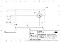
Horizontal distance between pulleys (P1, P2) is 58mm. Vertical distance between pulleys (P1, P2) is w = 9.5mm.
Pulleys and Belt are GT2, 2mm pitch. Belt width, 6mm. Belt thickness, 1.38mm (0.76 tooth).
Wrap angle in both pulleys is larger than 60deg. At least 6 teeth in contact with the pulley at any given time. In practice that means you want a minimum of a 12 tooth pulley, and usually try to get at least 18 teeth.
Outer Diameter of pulleys:
P(T) | OD(mm)
16 | 10.2
20 | 12.7
36 | 22.9
40 | 25.5
Belt calculation (according to calculator):
Ratio | P1(T) | P2(T) | Belt(T) | L(mm)
2.25|16|36|85/86|58.65/59.66
1.8|20|36|86/87/88|57.78/58.78/59.78
2.5|16|40|87/88|58.5/59.5
2|20|40|89/90|58.65/59.66
Motor Maximun no-load speed, 200RPM = 1200deg/s Motor Maximum stall-torue, 1.2Nm

Position of idler do not care, or min 1.3*P1, max 1.5*P1 (for 20T, ~16mm/~20mm).
Belt gear selection:
- 20/36 with 1.8 ratio and 86T/172mm belt without idler
- 20/40 with 2 ratio and 90T/190mm belt with idler
To calculate Deflection force, (page T-31, sdp - design-guidelines)
- Y = 2.05, Tst = 1.3kg
- span length, t = 57.64mm
- Belt pitch length, L = 180mm
- Fd,min =
- Fd,max =
- 2.8kg Working Tension [shapeoko - Belts and Pulleys](https://www.shapeoko.com/wiki/index.php/Belts_and_Pulleys#Tensile_Cord_Materials)
  P3

 /  \

P1  P2

    |

    P4-P5
- Determination of design load
According to perfomance graph of DC motor, the optimal output power is Tm = 0.6Nm with efficiency of 0.2 and 100RPM = 600deg/s. Select a service factor of 1.5 (service factors between 1.5 and 2.0 are generally recommended when designing small pitch synchronous drives). Tpeak = SF*Tm = 1.5*0.6 = 0.9Nm
- Choice of belt pitch
Due to backslash and accuracy in both directions of movements and volume constrains, we choose GT2, pitch 2mm.
- Check belt pitch selection based on individual graphs
Due to Tpeak = 0.9Nm No-load speed,(Speed of fastest shaft) = 100RPM = 600deg/s GT2 pitch 2mm belt is the better solution for our application.
- Determine speed ratio
Speed ratio 1.8-2.25 according to specification of output rotation speed of 5deg/s.
- Check belt speed
V(m/s) = 0.0000524 x pulley PD (mm) x pulley rpm = 0.066548m/s Belt speeds up to 6,500 fpm (33.02 m/s) do not require special pulleys.
- Determine belt length
Table 'Belt calculation (according to calculator)' Teeth in mesh: 9
- Determine the belt width
From Table 43 torque = 0.17Nm Length Correction Factor = 0.9 width multiplier = 1.00 torque*Length Correction Factor*width multiplier = 0.17*0.9*1.00 = 0.153Nm Teeth in mesh: 9 Tpeak = 0.9Nm, so belt width is nice for our application
- Check the number of teeth in mesh
Teeth in mesh: 9 according to calculator
- Determine proper belt installation tension
SECTION 10, on page T50, look at 'To calculate Deflection force, (page T-31, sdp - design-guidelines)'
- Y = 2.05, Tst = 0.812*DQ/d + mS^2 = 12.8lb + 0 = 5.8kg
- DQ = Tpeak = 0.9Nm = 7.9lb-in
- d = 12.7mm = 0.5in
- S = (0.5*100/3.82)/1000 = 0.0131ft/min
- m = 0.039
- span length, t = sqrt(CD^2 - (PD-pd/2)^2) = 57.64mm
- Belt pitch length, L = 180mm
- t/L = 0.32
- Fd,min = 0.8lb = 0.36kg
- Fd,max = 0.9lb = 0.41kg
- Safety factor 1.5
- P2 timing pulley torque - Maximum radial load of timing belt ball bearing 625zz
Tpeak = 0.9Nm TorqueP2 = 2*0.9Nm = 1.8Nm, PDp2 = 25.5mm Radial static load of 625ZZ is 0.38kN T-39
- Maximum thrust load of timing belt ball bearing 625zz
- Maximum radial and thrust load of output ball bearings 6008zz
Calculate or evaluate correct loads for deep groove ball bearings radial static load = 11.6kN thrust static load = 0.7*11.6kN = 8.12kN This type of construction permits the bearings to support relatively high thrust load in either direction. In fact the thrust load capacity is about 70% of the radial load capacity. A ball bearing primarily designed to support radial load can also support high thrust load; because only few balls carry the radial load, whereas all the balls can withstand the thrust load.
- Maximum self-locking or back-drivable torque of gear box (according to more weak component)
It necessary to achieve [specs](https://community.libre.space/t/satnogs-rotator-version-3/226), 60Nm (6Kg in 1 meter)
- Nominal torque of drivable torque of gear box (according to more weak component) and maximum rotational speed of gear box
Notes:
- sdp distance calculator
- belt GT2-6mm wide, 172mm
- belt GT2-6mm wide, 180mm
- idler pulley, no-teeth-ID3mm-OD18mm
- brecoflex - design-guidelines
- shreegeeimpex - design-guidelines
- sdp - design-guidelines
Motor Specification
General Specification about motors. The voltage and current consumption also it depends from the motor controller which is (maybe) different from SatNOGS Rotator Controller.
| Specification | Value |
|---|---|
| Min-Max Stall Torque (Nm) | 0.4 - 1.5 |
| Min-Max Speed (RPM) | 100 - 200 |
| Size (mm) (LxWxH) | 47x42x64 |
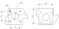
Motor mount dimensions
Maximum Motor Height


Worm Gear Box Calculations
- Gear ratio: i12 = 30
- Angle between axis of gears: δ = 90 deg
- Number of threads in worm: If i12 >= 30 then z1 = 1
- Number of teeth in worm wheel: z2 = i12*z1 = 30
- Center distance: initial case a = 45.5 mm
- Worm reference diameter: AGMA d01>= 11.5*(a/25.4)^0.875 = 19.15 mm, so d01 = 19.5mm
- Worm wheel reference: d02 = 2*a - d01 = 71.5 mm
- Axial module: ms = d02/z2 = 2.38 , so ms = 2.5
Recalculate d02, a with new axial module
- d02 = z2*ms = 75mm, a = (d02+d01)/2 = 47.25mm
- Axial pitch: ts = π*ms = 7.854mm
- Reference lead angle: γ0 = atan(d02/(i12*d01)) = 7.3 deg
- Worm tip diameter: dk1 = d01 + 2*hk = 24.5mm
- Worm teeth reference addendum in axial section: hk = hk* *ms = 2.5mm
- Worm tooth reference addendum coefficient: hk* = 1
- Worm root diameter: df1 = d01 - 2*hf = 13.5mm
- Worm tooth reference dedendum: hf = hf* _ms = 1.2_ms = 3mm
- Dedendum coefficient: hf* = 1.2
- Worm length: L = 2.5_ms_sqrt(z2+2) = 35.36mm
- Worm tooth thickness: smx1 = smx1* * ts = 3.927mm
- Tooth thickness coefficient: smx1* = 0.5
- Normal pressure angle: aon = 20 deg
- Worm wheel throat diameter: dk2 = d02+2*hk = 80mm
- Worm wheel root diameter: df2 = d02 - 2*hf = 69mm
- Worm wheel outside diameter: de2 = dk2 + 2*mx = 83.5mm
- Worm wheel tooth external addendum: mx = n*ms, 0.4<=n<=1.5
- Effective worm wheel face width: b2H,max = sqrt((2_a - df2)^2 - (2_a - de2)^2) = 23mm