Difference between revisions of "SatNOGS Rotator Controller"
(→Micro controller) |
(→Build sequence) |
||
| Line 41: | Line 41: | ||
* Make sure you have a [[SatNOGS Rotator v3|mechanical assembly]] of the rotator constructed and ready | * Make sure you have a [[SatNOGS Rotator v3|mechanical assembly]] of the rotator constructed and ready | ||
* Buy the PCB. [https://oshpark.com OshPark], [http://dirtypcbs.com DirtyPCBs.com], [https://www.elecrow.com/ Elecrow].com] have been used in the past with good results. | * Buy the PCB. [https://oshpark.com OshPark], [http://dirtypcbs.com DirtyPCBs.com], [https://www.elecrow.com/ Elecrow].com] have been used in the past with good results. | ||
| + | * Get all the necessary components according to BOM from latest tag (or the version that you want to build), [https://gitlab.com/librespacefoundation/satnogs/satnogs-rotator-controller/tags Gitlab Tags] | ||
* Assemble the PCB, by soldering the components | * Assemble the PCB, by soldering the components | ||
* Burn the firmware | * Burn the firmware | ||
Revision as of 08:44, 23 April 2018
| SatNOGS Rotator Controller | |
|---|---|
| Information | |
| Type: | Rotator Controller for SatNOGS rotator. |
| Cost: | ? |
| Release Information | |
| Status: | Working |
| Latest Release: | [v2 v2] |
| Repository: | SatNOGS Rotator Controller |
| Documentation: | SatNOGS wiki |

Contents
Intro
SatNOGS Rotator Controller refers to the set of electronics designed to operate a SatNOGS Rotator. There have been multiple iterations of the rotator controller design, but the modularity of the approach enables operations between different versions of the controller and the rotator. Since the start of 2016, the rotator controller design is able to facilitate a DC-motors or stepper-motors rotator design. We intend to keep this modularity for the electronics and firmware design to facilitate the variety of build by our community.
Rotator Controller v2


The PCB are tested in this ground station.
Features
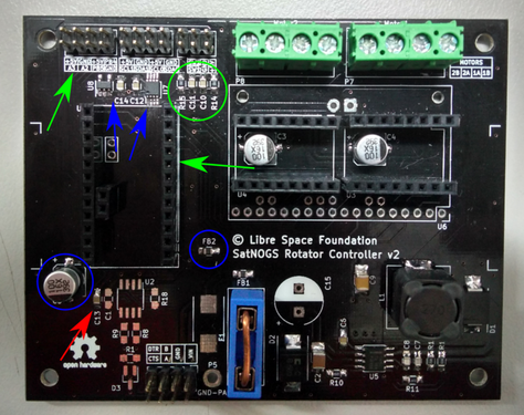
- It is designed to fit the entire electronics needed to control rotator in Euroboard 80x50 mm.
- Main micro-controller is Arduino pro-mini, SparkFun's Arduino Pro Mini 328 dev-board with ATmega328p.
- The modular design includes plug-in either DRV8825/A4988 or DC motor drivers (MC33926).
- The power supply in embed in the same board in contrast with previous version.
- Filter in power supply of micro controller.
- It has an I2C multiplexer to connect I2C encoders AS5601 (same ID) to get position feedback for each axis.
- A temperature sensor TC-74 monitoring the temperature inside the controller box in order to protect them from over-
temperatureheating. - More dev-pins to connect other peripherals like IMU, LCD display.
- Pins with RC-Low Pass filter for end-stops.
- Default communication interface is RS-485 but it can
bealso be used as a UART. - Avoid connection with GNDD directly with motor GND use keep out area.
- Electrolytic capacitor and TVS-diode in PSU input
- Flashed either by using UART or ISP header
Build sequence
- Make sure you have a mechanical assembly of the rotator constructed and ready
- Buy the PCB. OshPark, DirtyPCBs.com, Elecrow.com] have been used in the past with good results.
- Get all the necessary components according to BOM from latest tag (or the version that you want to build), Gitlab Tags
- Assemble the PCB, by soldering the components
- Burn the firmware
- Using the wiring diagram, connect the controller to the Rotator
- You are ready! Proceed with testing
Microcontroller
Microcontroller
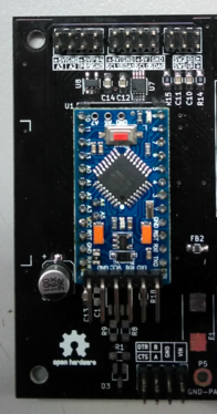
Microcontroller Orientation
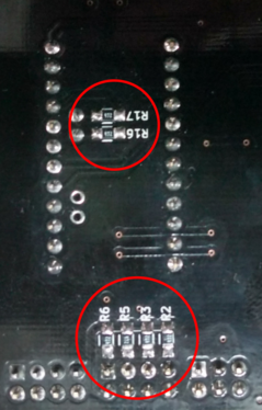
I2C pull-up resistors


The main micro-controller of the board is arduino pro-mini 5V@16MHz, ATmega328P. Some clones do not use correct parts, like the original one, and the result is, when it powers up with +12V, burned. Some examples,
One Solution is not use clones, use Sparkfun's arduiuno pro-mini 5V@16MHz, ATmega328P The second solution is to add a LDO, like MIC5205.
The power consumption in +5V is:
| - | QTY. | VCC(V) | IDD(mA) | Total(mA) |
|---|---|---|---|---|
| AS5601 | 2 | 5 | 6.5 | 13 |
| PCA9540B | 1 | 5 | 0.1 | 0.1 |
| SN65HVD485E | 1 | 5 | 2 | 2 |
| TC74 | 1 | 5 | 0.35 | 0.35 |
| arduino pro mini | 1 | 5 | 20 | 20 |
| MC33926 | 2 | 5 | 0.2 | 0.4 |
| DRV8825 | 2 | 5 | 0.1 | 0.2 |
The LDO MIC5205 guaranteed 150mA output, for Stepper motors ~35-40mA, for DC motors ~35-40mA.
Motor Specification
Maximum specification
- rotation speed: ~1200(200RPM) deg/s (after 1.8*30 = 54 gear reduction ~20deg/s and we want 5deg/s according to v3 rotator specification
- stall torque: 1.2Nm (after 1.8*30 = 54 gear reduction 64.5Nm)
Minimum specification
- rotation speed: ~360(60RPM) deg/s (after 1.8*30 = 54 gear reduction ~6.5deg/s and we want 5deg/s according to v3 rotator specification
- stall torque: 0.48Nm (after 1.8*30 = 54 gear reduction 25.92Nm)
You can design an adapter, to mount any motor to motor mount, like dc motor flange. This is the motor mount.
The DC motor that we use is 50:1 Metal Gearmotor 37Dx54L mm,
- Size: 37D x 54L mm
- Weight: 195 g
- Shaft diameter: 6 mm
- Free-run speed @ 12V: 200 rpm
- Free-run current @ 12V: 300 mA
- Stall current @ 12V: 5000 mA
- Stall torque @ 12V: 1.2Nm
The stepper motor that we use is Nema 17 Bipolar 59Ncm,
- Size: ▱42 x 48 mm
- Weight: 390 g
- Shaft diameter: 5 mm
- Step Angle: 1.8 deg
- Nominal speed @ 12V: 720deg/s
- Rated Current/phase: 2.0A
- Stall torque @ 12V: 0.59Nm
Motor Drivers
Stepper motor driver


For the stepper motor driver 2 options are tested, DRV8825 and A4988. For both options it is necessary to solder:
- 2 electrolytic capacitors C3, C4 100uF
- 4 single 0.1" male connectors for U3, U4
- 2 fixed terminal blocks, Phoenix 1985467
- 6 jumpers to adjust the micro-step, default option is Full Step
- Not solder 2 resistors 100k, R4, R7
Be careful:
- adjust the current (current limiting) for stepper motors
- add a heat-sink.
- plug the stepper motor drivers
| JP3/JP6 | JP2/JP5 | JP1/JP4 | Microstep Resolution |
| Low | Low | Low | Full step |
| High | Low | Low | Half step |
| Low | High | Low | 1/4 step |
| High | High | Low | 1/8 step |
| Low | Low | High | 1/16 step |
| High | Low | High | 1/32 step |
| Low | High | High | 1/32 step |
| High | High | High | 1/32 step |
DC motor driver
The DC motor controller is Dual MC33926 Motor Driver Carrier
- Motor driver: MC33926
- Motor channels: 2
- Minimum operating voltage: 5V
- Maximum operating voltage: 28V
- Operating voltage: 12V
- Continuous output current per channel: 2.5A
- Current sense: 0.525 V/A
- Maximum PWM frequency: 20 kHz
- Operating PWM frequency: 3921.5Hz (~4kHz)
- Minimum logic voltage: 2.5V
- Operating logic voltage: 5V
- Maximum logic voltage: 5.5V
Communication
UART


To use UART:
- solder JP7 and JP8
- solder pin header 0.1" female connector
- not solder C1, U2, R18, R9, R8, R1, D3
- A is TX and B is RX
RS-485
WIP
Power Supply

Recommended power supply for rotator controller is: 48V @ 1A DC. A good choice is MEAN WELL LRS-50-48
The switching power supply could get as input voltage, 19-60V DC. In different input voltages, must be change the components like D4 and F1.
Endstops
- Mechanical Endstops

Encoders
For stepper motor setup is optional (AS5601 encoder).
WIP
Wiring

Rotator Controller enclosure - Placement
WIP
Firmware and Pin Assignments
Firmware
More info in gitlab repository For DC motors
Pins Configuration
- M1IN1 6, Step or PWM1
- M1IN2 5, Direction or PWM2
- M1SF 7, Status flag
- M1FB A1, Load measurment
- M2IN1 11, Step or PWM1
- M2IN2 3, Direction or PWM2
- M2SF 10, Status flag
- M2FB A0, Load measurment
- MOTOR_EN 8, Enable/Disable motors
- SW1 9, Endstop for axis 1
- SW2 4, Endstop for axis 2
- RS485_DIR 2, RS485 Half Duplex direction pin
- SDA_PIN 3, Data I2C pin
- SCL_PIN 4, Clock I2C pin
- PIN12 12, Digital output pin
- PIN13 13, Digital output pin
- A2 A2, Analog input pin
- A3 A3, Analog input pin
Pre-Flight Check
Need to add testing procedure here.
How do you align the rotator?
Rotator Controller v1