Difference between revisions of "SatNOGS Arduino Uno/CNC Shield Based Rotator Controller"
(Added some images) (Tag: Visual edit) |
m (I'm putting the information about micro stepping jumpers that is not mentioned in the procedure.) (Tag: Visual edit) |
||
| (2 intermediate revisions by 2 users not shown) | |||
| Line 1: | Line 1: | ||
{{DISPLAYTITLE:SatNOGS Arduino Uno CNC Shield Based Rotator Controller}} | {{DISPLAYTITLE:SatNOGS Arduino Uno CNC Shield Based Rotator Controller}} | ||
| − | === Controlling the rotator as a stand alone system using GPredict === | + | ===Controlling the rotator as a stand alone system using GPredict=== |
The SatNOGS rotator is primarily designed to be used as a system component that is part of a SatNOGS ground station. There may be occasion when it is desirable to have a stand alone ground station that is removed from the SatNOGS network. This can be done using existing equipment but can also be simplified using off the shelf components. | The SatNOGS rotator is primarily designed to be used as a system component that is part of a SatNOGS ground station. There may be occasion when it is desirable to have a stand alone ground station that is removed from the SatNOGS network. This can be done using existing equipment but can also be simplified using off the shelf components. | ||
| Line 8: | Line 8: | ||
We will need slightly different hardware and modified software to achieve this, the main changes will be to remove the RS485 and watchdog parts of the firmware. We will be using the following items: | We will need slightly different hardware and modified software to achieve this, the main changes will be to remove the RS485 and watchdog parts of the firmware. We will be using the following items: | ||
| − | ==== Hardware ==== | + | ====Hardware==== |
| − | # SatNOGS Rotator V3.1 hardware | + | |
| − | # Arduino Uno R3 | + | #SatNOGS Rotator V3.1 hardware |
| − | # CNC Shield V3 with A4988 drivers | + | #Arduino Uno R3 |
| − | # NEMA 17 Stepper Motors | + | #CNC Shield V3 with A4988 drivers |
| − | # 2x microswitches | + | #NEMA 17 Stepper Motors |
| − | # Suitable 12v power supply (The shield will accept between 12v and 36v) | + | #2x microswitches |
| − | # Cables to connect the Arduino to the PC | + | #Suitable 12v power supply (The shield will accept between 12v and 36v) |
| + | #Cables to connect the Arduino to the PC | ||
[[File:Arduino CNC Shield.png|centre|Bare CNC Shield]] | [[File:Arduino CNC Shield.png|centre|Bare CNC Shield]] | ||
| Line 21: | Line 22: | ||
[[File:A4988 Drivers.png|centre]] | [[File:A4988 Drivers.png|centre]] | ||
| − | ==== Software ==== | + | ====Software==== |
For the purposes of this article we will be using Windows software. The same result can be achieved with Linux or Mac OS but for clarity these options have been ignored for the time being. We will need: | For the purposes of this article we will be using Windows software. The same result can be achieved with Linux or Mac OS but for clarity these options have been ignored for the time being. We will need: | ||
| − | |||
| − | |||
| − | |||
| − | |||
| − | |||
| − | === Method === | + | #A copy of the Arduino IDE (version 1.8.5 has been used as part of this tutorial) |
| + | #GPredict | ||
| + | #Hamlib | ||
| + | #A text editor such as Notepad++ for a small script | ||
| + | #[https://gitlab.com/Quartapound/satnogs-rotator-firmware You can find the edited sketch and libraries in the following Fork : https://gitlab.com/Quartapound/satnogs-rotator-firmware] | ||
| + | |||
| + | ===Method=== | ||
| − | ==== Hardware setup ==== | + | ====Hardware setup==== |
We will not be using the custom SatNOGS PCB. Instead this set up uses an Arduino Uno and CNC motor shield. There is very little assembly required but depending on how and where you buy from will depend on the amount of assembly is required. Typically the Arduino will need no assembly, The motor shield will need two A4988 drivers (these can come as part of the package). These are used in the X & Y headers as per the photograph below. The drivers fit into the female headers, note that there are jumper headers below these drivers that are used for stepping control. We will also be attaching the stepper motor cables to the male headers to the left of the driver boards. | We will not be using the custom SatNOGS PCB. Instead this set up uses an Arduino Uno and CNC motor shield. There is very little assembly required but depending on how and where you buy from will depend on the amount of assembly is required. Typically the Arduino will need no assembly, The motor shield will need two A4988 drivers (these can come as part of the package). These are used in the X & Y headers as per the photograph below. The drivers fit into the female headers, note that there are jumper headers below these drivers that are used for stepping control. We will also be attaching the stepper motor cables to the male headers to the left of the driver boards. | ||
[[File:Assembled CNC Shield.png|centre]] | [[File:Assembled CNC Shield.png|centre]] | ||
| Line 48: | Line 50: | ||
The setup is very basic but be careful not to bend pins as this can be easily done if too much pressure is put on the boards when things are no aligned. They aren't always perfect! | The setup is very basic but be careful not to bend pins as this can be easily done if too much pressure is put on the boards when things are no aligned. They aren't always perfect! | ||
| + | |||
| + | Micro Stepping jumpers under each pololu, need to be 1/8 (jumpers M0 and M1 put it and free the M2). | ||
In the end you should have: | In the end you should have: | ||
| − | |||
| − | |||
| − | |||
| − | |||
| − | + | *Azimuth Stepper Driver/motor connected to Y port on CNC Board | |
| + | *Elevation Stepper Driver/motor connected to X port on CNC Board | ||
| + | *The End stop switch for elevation is connected to the X end stop on the CNC board (+ or -) | ||
| + | *The End stop switch for azimuth is connected to the Y end stop on the CNC board (+ or -) | ||
| − | ===== Code modifications ===== | + | ====Software setup==== |
| + | |||
| + | =====Code modifications===== | ||
For the time being there is no fork of the firmware in the repositories. This may change in the future but for the time being a small series of changes are required to achieve results. We will need to modify two elements of the firmware, easycomm.h and rotator_pins.h. These changes are necessary to stop their being conflicts with the communication between boards and PC as well as re-assigning pins to match the CNC shield. We'll modify the rotator_pins.h first. Note the use of comments (//) to remove lines of code. We have also changed pin designation to match the shield. | For the time being there is no fork of the firmware in the repositories. This may change in the future but for the time being a small series of changes are required to achieve results. We will need to modify two elements of the firmware, easycomm.h and rotator_pins.h. These changes are necessary to stop their being conflicts with the communication between boards and PC as well as re-assigning pins to match the CNC shield. We'll modify the rotator_pins.h first. Note the use of comments (//) to remove lines of code. We have also changed pin designation to match the shield. | ||
| Line 501: | Line 506: | ||
#endif /* LIBRARIES_EASYCOMM_H_ */ | #endif /* LIBRARIES_EASYCOMM_H_ */ | ||
| − | ===== Software to install ===== | + | =====Software to install===== |
Final pieces to the preparation work are to install a couple of pieces of software. firstly Hamlib. This will be used to communicate between GPredict and the Arduino. Secondly we will install the main prediction software, GPredict. We will not be going into detail about setup of GPredict but assume that you have followed the installation guide and had a play around with it so you can understand what it is and how it works. | Final pieces to the preparation work are to install a couple of pieces of software. firstly Hamlib. This will be used to communicate between GPredict and the Arduino. Secondly we will install the main prediction software, GPredict. We will not be going into detail about setup of GPredict but assume that you have followed the installation guide and had a play around with it so you can understand what it is and how it works. | ||
| Line 522: | Line 527: | ||
That's it for setup. next we will test the system | That's it for setup. next we will test the system | ||
| − | === Testing === | + | ===Testing=== |
We will need to do a few things to get the system running. | We will need to do a few things to get the system running. | ||
| − | # Start the .bat file | + | #Start the .bat file |
| − | # In GPredict open up the Antenna module and click Engage | + | #In GPredict open up the Antenna module and click Engage |
| − | # You should see that in the batch file output a series of commands being sent to the Arduino | + | #You should see that in the batch file output a series of commands being sent to the Arduino |
| − | # Check that both the Az and Ele work correctly by manually driving the rotator | + | #Check that both the Az and Ele work correctly by manually driving the rotator |
| + | |||
[[File:GPredict Antenna Control.png|centre]] | [[File:GPredict Antenna Control.png|centre]] | ||
Occasionally this might not work first time. A restart of both hamlib and Gpredict worked | Occasionally this might not work first time. A restart of both hamlib and Gpredict worked | ||
| − | === Tweaks === | + | ===Tweaks=== |
There is a huge variety in parts that can get bought, here are a few tweaks that may be necessary. | There is a huge variety in parts that can get bought, here are a few tweaks that may be necessary. | ||
| Line 543: | Line 549: | ||
define DEFAULT_HOME_STATE LOW ///< Change to LOW according to Home sensor | define DEFAULT_HOME_STATE LOW ///< Change to LOW according to Home sensor | ||
| − | === Operation === | + | ===Operation=== |
| − | Operating is as simple as selecting a satellite from GPredict and then selecting track. The rotator will then follow that satellite or object. | + | Operating is as simple as selecting a satellite from GPredict and then selecting track. The rotator will then follow that satellite or object. |
{{DEFAULTSORT:SatNOGS Arduino Uno CNC Shield Based Rotator Controller}} | {{DEFAULTSORT:SatNOGS Arduino Uno CNC Shield Based Rotator Controller}} | ||
| + | |||
| + | [[Category:Build]] | ||
| + | [[Category:Hardware]] | ||
| + | |||
__FORCETOC__ | __FORCETOC__ | ||
Latest revision as of 22:23, 24 March 2020
Contents
Controlling the rotator as a stand alone system using GPredict
The SatNOGS rotator is primarily designed to be used as a system component that is part of a SatNOGS ground station. There may be occasion when it is desirable to have a stand alone ground station that is removed from the SatNOGS network. This can be done using existing equipment but can also be simplified using off the shelf components.
The following information is to connect your Rotator controller DIRECTLY TO A PC. If you'd like to still use it with the Raspberry Pi then you must keep the RS485 protocol in place.
We will need slightly different hardware and modified software to achieve this, the main changes will be to remove the RS485 and watchdog parts of the firmware. We will be using the following items:
Hardware
- SatNOGS Rotator V3.1 hardware
- Arduino Uno R3
- CNC Shield V3 with A4988 drivers
- NEMA 17 Stepper Motors
- 2x microswitches
- Suitable 12v power supply (The shield will accept between 12v and 36v)
- Cables to connect the Arduino to the PC
Software
For the purposes of this article we will be using Windows software. The same result can be achieved with Linux or Mac OS but for clarity these options have been ignored for the time being. We will need:
- A copy of the Arduino IDE (version 1.8.5 has been used as part of this tutorial)
- GPredict
- Hamlib
- A text editor such as Notepad++ for a small script
- You can find the edited sketch and libraries in the following Fork : https://gitlab.com/Quartapound/satnogs-rotator-firmware
Method
Hardware setup
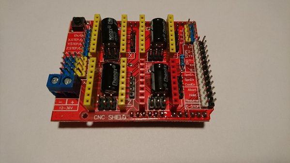
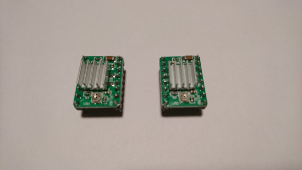
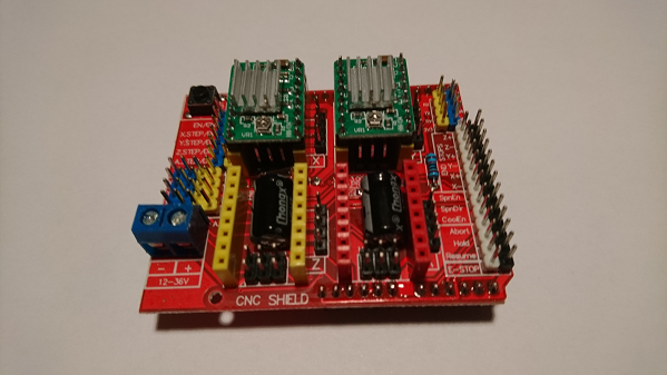
We will not be using the custom SatNOGS PCB. Instead this set up uses an Arduino Uno and CNC motor shield. There is very little assembly required but depending on how and where you buy from will depend on the amount of assembly is required. Typically the Arduino will need no assembly, The motor shield will need two A4988 drivers (these can come as part of the package). These are used in the X & Y headers as per the photograph below. The drivers fit into the female headers, note that there are jumper headers below these drivers that are used for stepping control. We will also be attaching the stepper motor cables to the male headers to the left of the driver boards.
Pinout of the 4 headers is as follows starting from the top (4 vertical pins to the left of the A4988 motor driver board, marked X,Y & Z)
Pin 1 - A
Pin 2 - A+
Pin 3 - B
Pin 4 - B+
This follows a convention so most steppers should plug directly into the header without any changes, but be aware that this is not always the case and that there may be some cases where pins are incorrectly noted and the steppers will drive in the opposite direction.
The setup is very basic but be careful not to bend pins as this can be easily done if too much pressure is put on the boards when things are no aligned. They aren't always perfect!
Micro Stepping jumpers under each pololu, need to be 1/8 (jumpers M0 and M1 put it and free the M2).
In the end you should have:
- Azimuth Stepper Driver/motor connected to Y port on CNC Board
- Elevation Stepper Driver/motor connected to X port on CNC Board
- The End stop switch for elevation is connected to the X end stop on the CNC board (+ or -)
- The End stop switch for azimuth is connected to the Y end stop on the CNC board (+ or -)
Software setup
Code modifications
For the time being there is no fork of the firmware in the repositories. This may change in the future but for the time being a small series of changes are required to achieve results. We will need to modify two elements of the firmware, easycomm.h and rotator_pins.h. These changes are necessary to stop their being conflicts with the communication between boards and PC as well as re-assigning pins to match the CNC shield. We'll modify the rotator_pins.h first. Note the use of comments (//) to remove lines of code. We have also changed pin designation to match the shield.
   /*!
   * @file rotator_pins.h
   *
   * It is a header file for pin mapping.
   *
   * Licensed under the GPLv3
   *
   */
   #ifndef ROTATOR_PINS_H_
   #define ROTATOR_PINS_H_
   //#define M1IN1 10 ///< Motor 1 PWM pin
   #define M1IN1 2 ///< Motor 1 PWM pin
   #define M1IN2 5  ///< Motor 1 PWM pin
   #define M1SF  7  ///< Motor 1 digital input, status flag for DC Motor Drivers
   #define M1FB  A1 ///< Motor 1 analog input, current/load feedback for DC Motor Drivers
   #define M2IN1 3 ///< Motor 2 PWM pin
   #define M2IN2 6  ///< Motor 2 PWM pin
   #define M2SF  7 ///< Motor 2 digital input, status flag for DC Motor Drivers
   #define M2FB  A0 ///< Motor 2 analog input, current/load feedback for DC Motor Drivers
#define MOTOR_EN 8 ///< Digital output, to enable the motors
   #define SW1 11 ///< Digital input, to read the status of end-stop for motor 1
   #define SW2 9 ///< Digital input, to read the status of end-stop for motor 2
#define RS485_DIR 2 ///< Digital output, to set the direction of RS485 communication
   #define SDA_PIN 3 ///< I2C data pin
   #define SCL_PIN 4 ///< I2C clock pin
   #define PIN12 12 ///< General purpose I/O pin
   #define PIN13 13 ///< General purpose I/O pin
   #define A2    A2 ///< General purpose I/O & analog pin
   #define A3    A3 ///< General purpose I/O & analog pin
#endif /* ROTATOR_PINS_H_ */
The next code edit will remove both the RS485 and watchdog elements from the easycomm.h code. This will allow the PC to talk directly to the Arduino and as such bypass the RPi. The edited code is below, note again the use of comments (//) to remove the lines
   /*!
   * @file easycomm.h
   *
   * It is a driver for easycomm 3 protocol as referred, in Hamlib.
   *
   * Licensed under the GPLv3
   *
   */
   #ifndef LIBRARIES_EASYCOMM_H_
   #define LIBRARIES_EASYCOMM_H_
   #include <Arduino.h>
   #include <WString.h>
   #include <avr/wdt.h>
   //#include "rs485.h"
   #include "rotator_pins.h"
   #include "globals.h"
   #define RS485_TX_TIME 9     ///< Delay "t"ms to write in serial for RS485 implementation
   #define BUFFER_SIZE   256   ///< Set the size of serial buffer
   #define BAUDRATE      19200 ///< Set the Baudrate of easycomm 3 protocol
//rs485 rs485(RS485_DIR, RS485_TX_TIME);
   /**************************************************************************/
   /*!
       @brief    Class that functions for easycomm 3 implementation
   */
   /**************************************************************************/
   class easycomm {
   public:
       /**************************************************************************/
       /*!
           @brief    Initialize the RS485 bus
       */
       /**************************************************************************/
       void easycomm_init() {
          // rs485.begin(BAUDRATE);
   	    Serial.begin(9600);
       }
       /**************************************************************************/
       /*!
           @brief    Get the commands from RS485 and response to the client
       */
       /**************************************************************************/
       void easycomm_proc() {
           char buffer[BUFFER_SIZE];
           char incomingByte;
           char *Data = buffer;
           char *rawData;
           static uint16_t BufferCnt = 0;
           char data[100];
           String str1, str2, str3, str4, str5, str6;
           // Read from serial
           while (Serial.available() > 0) {
               incomingByte = Serial.read();
// Read new data, '\n' means new pacakage
if (incomingByte == '\n' || incomingByte == '\r') {
buffer[BufferCnt] = 0;
if (buffer[0] == 'A' && buffer[1] == 'Z') {
if (buffer[2] == ' ' && buffer[3] == 'E' &&
buffer[4] == 'L') {
// Send current absolute position in deg
str1 = String("AZ");
str2 = String(control_az.input, 1);
str3 = String(" EL");
str4 = String(control_el.input, 1);
str5 = String("\n");
Serial.print(str1 + str2 + str3 + str4 + str5);
} else {
// Get the absolute position in deg for azimuth
rotator.control_mode = position;
rawData = strtok_r(Data, " ", &Data);
strncpy(data, rawData + 2, 10);
if (isNumber(data)) {
control_az.setpoint = atof(data);
}
// Get the absolute position in deg for elevation
rawData = strtok_r(Data, " ", &Data);
if (rawData[0] == 'E' && rawData[1] == 'L') {
strncpy(data, rawData + 2, 10);
if (isNumber(data)) {
control_el.setpoint = atof(data);
}
}
}
} else if (buffer[0] == 'E' && buffer[1] == 'L') {
// Get the absolute position in deg for elevation
rotator.control_mode = position;
rawData = strtok_r(Data, " ", &Data);
if (rawData[0] == 'E' && rawData[1] == 'L') {
strncpy(data, rawData + 2, 10);
if (isNumber(data)) {
control_el.setpoint = atof(data);
}
}
} else if (buffer[0] == 'V' && buffer[1] == 'U') {
// Elevation increase speed in mdeg/s
rotator.control_mode = speed;
strncpy(data, Data + 2, 10);
if (isNumber(data)) {
// Convert to deg/s
control_el.setpoint_speed = atof(data) / 1000;
}
} else if (buffer[0] == 'V' && buffer[1] == 'D') {
// Elevation decrease speed in mdeg/s
rotator.control_mode = speed;
strncpy(data, Data + 2, 10);
if (isNumber(data)) {
// Convert to deg/s
control_el.setpoint_speed = - atof(data) / 1000;
}
} else if (buffer[0] == 'V' && buffer[1] == 'L') {
// Azimuth increase speed in mdeg/s
rotator.control_mode = speed;
strncpy(data, Data + 2, 10);
if (isNumber(data)) {
// Convert to deg/s
control_az.setpoint_speed = atof(data) / 1000;
}
} else if (buffer[0] == 'V' && buffer[1] == 'R') {
// Azimuth decrease speed in mdeg/s
rotator.control_mode = speed;
strncpy(data, Data + 2, 10);
if (isNumber(data)) {
// Convert to deg/s
control_az.setpoint_speed = - atof(data) / 1000;
}
} else if (buffer[0] == 'S' && buffer[1] == 'A' &&
buffer[2] == ' ' && buffer[3] == 'S' &&
buffer[4] == 'E') {
// Stop Moving
rotator.control_mode = position;
str1 = String("AZ");
str2 = String(control_az.input, 1);
str3 = String(" EL");
str4 = String(control_el.input, 1);
str5 = String("\n");
Serial.print(str1 + str2 + str3 + str4 + str5);
control_az.setpoint = control_az.input;
control_el.setpoint = control_el.input;
} else if (buffer[0] == 'R' && buffer[1] == 'E' &&
buffer[2] == 'S' && buffer[3] == 'E' &&
buffer[4] == 'T') {
// Reset the rotator, go to home position
str1 = String("AZ");
str2 = String(control_az.input, 1);
str3 = String(" EL");
str4 = String(control_el.input, 1);
str5 = String("\n");
Serial.print(str1 + str2 + str3 + str4 + str5);
rotator.homing_flag = false;
} else if (buffer[0] == 'P' && buffer[1] == 'A' &&
buffer[2] == 'R' && buffer[3] == 'K' ) {
// Park the rotator
rotator.control_mode = position;
str1 = String("AZ");
str2 = String(control_az.input, 1);
str3 = String(" EL");
str4 = String(control_el.input, 1);
str5 = String("\n");
Serial.print(str1 + str2 + str3 + str4 + str5);
control_az.setpoint = rotator.park_az;
control_el.setpoint = rotator.park_el;
} else if (buffer[0] == 'V' && buffer[1] == 'E') {
// Get the version if rotator controller
str1 = String("VE");
str2 = String("SatNOGS-v2.2");
str3 = String("\n");
Serial.print(str1 + str2 + str3);
} else if (buffer[0] == 'I' && buffer[1] == 'P' &&
buffer[2] == '0') {
// Get the inside temperature
str1 = String("IP0,");
str2 = String(rotator.inside_temperature, DEC);
str3 = String("\n");
Serial.print(str1 + str2 + str3);
} else if (buffer[0] == 'I' && buffer[1] == 'P' &&
buffer[2] == '1') {
// Get the status of end-stop, azimuth
str1 = String("IP1,");
str2 = String(rotator.switch_az, DEC);
str3 = String("\n");
Serial.print(str1 + str2 + str3);
} else if (buffer[0] == 'I' && buffer[1] == 'P' &&
buffer[2] == '2') {
// Get the status of end-stop, elevation
str1 = String("IP2,");
str2 = String(rotator.switch_el, DEC);
str3 = String("\n");
Serial.print(str1 + str2 + str3);
} else if (buffer[0] == 'I' && buffer[1] == 'P' &&
buffer[2] == '3') {
// Get the current position of azimuth in deg
str1 = String("IP3,");
str2 = String(control_az.input, 2);
str3 = String("\n");
Serial.print(str1 + str2 + str3);
} else if (buffer[0] == 'I' && buffer[1] == 'P' &&
buffer[2] == '4') {
// Get the current position of elevation in deg
str1 = String("IP4,");
str2 = String(control_el.input, 2);
str3 = String("\n");
Serial.print(str1 + str2 + str3);
} else if (buffer[0] == 'I' && buffer[1] == 'P' &&
buffer[2] == '5') {
// Get the load of azimuth, in range of 0-1023
str1 = String("IP5,");
str2 = String(control_az.load, DEC);
str3 = String("\n");
Serial.print(str1 + str2 + str3);
} else if (buffer[0] == 'I' && buffer[1] == 'P' &&
buffer[2] == '6') {
// Get the load of elevation, in range of 0-1023
str1 = String("IP6,");
str2 = String(control_el.load, DEC);
str3 = String("\n");
Serial.print(str1 + str2 + str3);
} else if (buffer[0] == 'I' && buffer[1] == 'P' &&
buffer[2] == '7') {
// Get the speed of azimuth in deg/s
str1 = String("IP7,");
str2 = String(control_az.speed, 2);
str3 = String("\n");
Serial.print(str1 + str2 + str3);
} else if (buffer[0] == 'I' && buffer[1] == 'P' &&
buffer[2] == '8') {
// Get the speed of elevation in deg/s
str1 = String("IP8,");
str2 = String(control_el.speed, 2);
str3 = String("\n");
Serial.print(str1 + str2 + str3);
} else if (buffer[0] == 'G' && buffer[1] == 'S') {
// Get the status of rotator
str1 = String("GS");
str2 = String(rotator.rotator_status, DEC);
str3 = String("\n");
Serial.print(str1 + str2 + str3);
} else if (buffer[0] == 'G' && buffer[1] == 'E') {
// Get the error of rotator
str1 = String("GE");
str2 = String(rotator.rotator_error, DEC);
str3 = String("\n");
Serial.print(str1 + str2 + str3);
} else if(buffer[0] == 'C' && buffer[1] == 'R') {
// Get Configuration of rotator
if (buffer[3] == '1') {
// Get Kp Azimuth gain
str1 = String("1,");
str2 = String(control_az.p, 2);
str3 = String("\n");
Serial.print(str1 + str2 + str3);
} else if (buffer[3] == '2') {
// Get Ki Azimuth gain
str1 = String("2,");
str2 = String(control_az.i, 2);
str3 = String("\n");
Serial.print(str1 + str2 + str3);
} else if (buffer[3] == '3') {
// Get Kd Azimuth gain
str1 = String("3,");
str2 = String(control_az.d, 2);
str3 = String("\n");
Serial.print(str1 + str2 + str3);
} else if (buffer[3] == '4') {
// Get Kp Elevation gain
str1 = String("4,");
str2 = String(control_el.p, 2);
str3 = String("\n");
Serial.print(str1 + str2 + str3);
} else if (buffer[3] == '5') {
// Get Ki Elevation gain
str1 = String("5,");
str2 = String(control_el.i, 2);
str3 = String("\n");
Serial.print(str1 + str2 + str3);
} else if (buffer[3] == '6') {
// Get Kd Elevation gain
str1 = String("6,");
str2 = String(control_el.d, 2);
str3 = String("\n");
Serial.print(str1 + str2 + str3);
} else if (buffer[3] == '7') {
// Get Azimuth park position
str1 = String("7,");
str2 = String(rotator.park_az, 2);
str3 = String("\n");
Serial.print(str1 + str2 + str3);
} else if (buffer[3] == '8') {
// Get Elevation park position
str1 = String("8,");
str2 = String(rotator.park_el, 2);
str3 = String("\n");
Serial.print(str1 + str2 + str3);
} else if (buffer[3] == '9') {
// Get control mode
str1 = String("9,");
str2 = String(rotator.control_mode);
str3 = String("\n");
Serial.print(str1 + str2 + str3);
}
} else if (buffer[0] == 'C' && buffer[1] == 'W') {
// Set Config
if (buffer[2] == '1') {
// Set Kp Azimuth gain
rawData = strtok_r(Data, ",", &Data);
strncpy(data, rawData + 4, 10);
if (isNumber(data)) {
control_az.p = atof(data);
}
} else if (buffer[2] == '2') {
// Set Ki Azimuth gain
rawData = strtok_r(Data, ",", &Data);
strncpy(data, rawData + 4, 10);
if (isNumber(data)) {
control_az.i = atof(data);
}
} else if (buffer[2] == '3') {
// Set Kd Azimuth gain
rawData = strtok_r(Data, ",", &Data);
strncpy(data, rawData + 4, 10);
if (isNumber(data)) {
control_az.d = atof(data);
}
} else if (buffer[2] == '4') {
// Set Kp Elevation gain
rawData = strtok_r(Data, ",", &Data);
strncpy(data, rawData + 4, 10);
if (isNumber(data)) {
control_el.p = atof(data);
}
} else if (buffer[2] == '5') {
// Set Ki Elevation gain
rawData = strtok_r(Data, ",", &Data);
strncpy(data, rawData + 4, 10);
if (isNumber(data)) {
control_el.i = atof(data);
}
} else if (buffer[2] == '6') {
// Set Kd Elevation gain
rawData = strtok_r(Data, ",", &Data);
strncpy(data, rawData + 4, 10);
if (isNumber(data)) {
control_el.d = atof(data);
}
} else if (buffer[2] == '7') {
// Set the Azimuth park position
rawData = strtok_r(Data, ",", &Data);
strncpy(data, rawData + 4, 10);
if (isNumber(data)) {
rotator.park_az = atof(data);
}
} else if (buffer[2] == '8') {
// Set the Elevation park position
rawData = strtok_r(Data, ",", &Data);
strncpy(data, rawData + 4, 10);
if (isNumber(data)) {
rotator.park_el = atof(data);
}
}
} else if (buffer[0] == 'R' && buffer[1] == 'S'
&& buffer[2] == 'T') {
// Custom command to test the watchdog timer routine
while(1)
;
} else if (buffer[0] == 'R' && buffer[1] == 'B') {
// Custom command to reboot the uC
wdt_enable(WDTO_2S);
while(1);
}
// Reset the buffer an clean the serial buffer
BufferCnt = 0;
Serial.flush();
} else {
// Fill the buffer with incoming data
buffer[BufferCnt] = incomingByte;
BufferCnt++;
}
}
}
   private:
       bool isNumber(char *input) {
           for (uint16_t i = 0; input[i] != '\0'; i++) {
               if (isalpha(input[i]))
                   return false;
           }
           return true;
       }
   };
#endif /* LIBRARIES_EASYCOMM_H_ */
Software to install
Final pieces to the preparation work are to install a couple of pieces of software. firstly Hamlib. This will be used to communicate between GPredict and the Arduino. Secondly we will install the main prediction software, GPredict. We will not be going into detail about setup of GPredict but assume that you have followed the installation guide and had a play around with it so you can understand what it is and how it works.
Install hamlib
Download the Hamblib software and follow the installation process. this may require you installing it with Administrator rights. using device manager find the port for the Arduino, for the purposes of this we will assume it is COM7
Using a text editor, like Notepad++, to create a file with the code below in it. Note where COM7 is and amend with your own COM port. Save as a batch file (i.e. with th extension .bat file in the same folder as rotctld (Usually found in C:\Program Files (x86)\hamlib-w64-3.2\bin )
rotctld -m 202 -r COM7 -s 9600 -T 127.0.0.1 -t 4533 -C timeout=500 -C retry=0 -vvvvvvvv > pause
Install GPredict
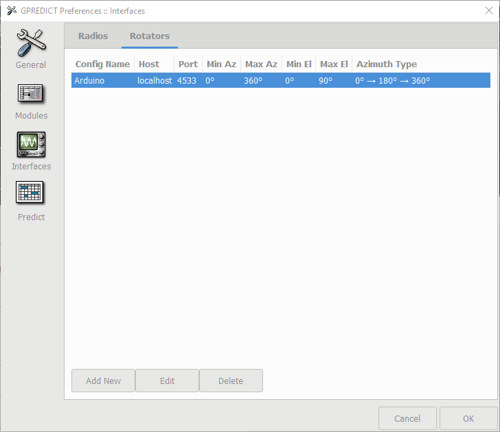
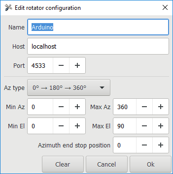
Download and install GPredict. Next we will need to add a rotator. Go to Edit > Preferences > Interfaces > Rotators > Add New
Give it a name. For example Arduino. The port is localhost 4533
That's it for setup. next we will test the system
Testing
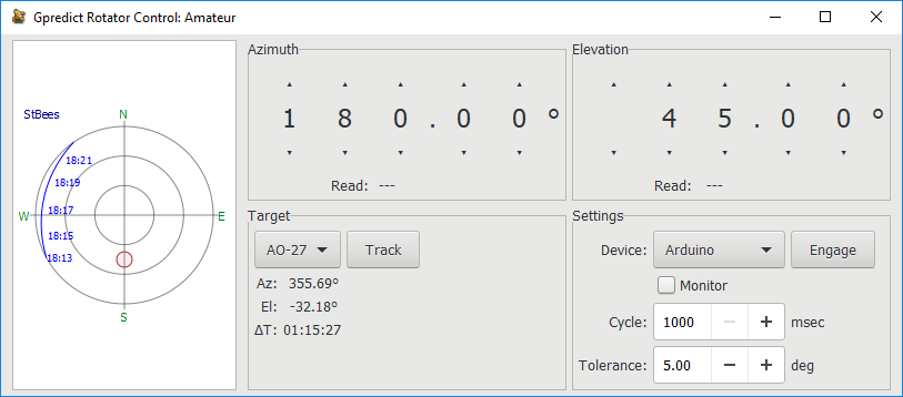
We will need to do a few things to get the system running.
- Start the .bat file
- In GPredict open up the Antenna module and click Engage
- You should see that in the batch file output a series of commands being sent to the Arduino
- Check that both the Az and Ele work correctly by manually driving the rotator
Occasionally this might not work first time. A restart of both hamlib and Gpredict worked
Tweaks
There is a huge variety in parts that can get bought, here are a few tweaks that may be necessary.
Motors are turning the wrong way - This may need the pins checking
It is only moving half the distance - Change the gear ratio in the main sketch
The limit switches are not working - Change the following code in the main sketch
define DEFAULT_HOME_STATE LOW ///< Change to LOW according to Home sensor
Operation
Operating is as simple as selecting a satellite from GPredict and then selecting track. The rotator will then follow that satellite or object.
