Contents
Introduction
The existing rotator controllers are old-fashioned and use obsolete technology, either in hardware or in software. Almost all the motor drivers are based on electromechanical switches like relays. This introduces limits to the usefulness in connection with satellite observations, and cause reduced accuracy in the movements of the rotator. In the following, we will be reviewing the three most popular commercially available rotator systems in the ham radio community:
- Yaesu G-5500
- SPID rotators
- SPX rotators,
Yaesu G-5500
Electronics
Yaesu G-5500 is an AZ/EL rotator. The datasheet states that it has AC motors (26V@2.8A, specifications of transformer for both motors), potentiometer (not multiturn) for position feedback which are operated with +6V, and the control loop is implemented with analog IC's (comparators and op-amps). Also, the system has end-stops in both axes in both directions (min-max), that immediately cut off the current to the motors. The connection to the client is implemented via a rotator interface, for example an ardushield that runs k3ng rotator firmware. The cost of the entire system is ~750$ including an analog controller.
Useful links:

Mechanical
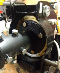
The gear box of the rotator it is a spur gear box. Almost all the gears are made from laser cut sheet metal, and the output gear is a stack of laser cut sheet metal gears. Another interesting thing is the brake system, which is a torsional spring in the motor axis, that blocks the movement from output to input. When a torque is applied from output to input, the torsional spring "opens" and blocks the rotation. A mechanical failure in of one brackets that mount the pins of the gears was observed in station 6 after a lot of observations (the oval hole). This problem is caused by the antennas being back-mounted without a counterbalance.
Yaesu G5500, Gear box

Yaesu G5500, Mechanical failure


Alternative Rotator Controllers
A list of available digital controllers:
- RT-21 Azimuth/Elevation, Green Heron Engineering LLC, 889$
- AZ-EL USB Rotor Controller AE-21
- DIY solution from ARRL
SPID rotators
This company it has two AZ/EL models:
Electronics
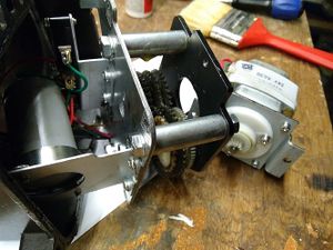
Both the models are using DC motors, according to the datasheets, BIG-RAS and RAS. The power consumption for both rotators is 12V@6-10A or 18V@6-11A. For the position sensor, a reed switch is used, one in each axis. This sensor is mounted in the first stage of a worm gear box (in total two worm gear boxes), with a total of 6 magnets that produce pulses with Vp-p according to the Vcc of the reed switch.
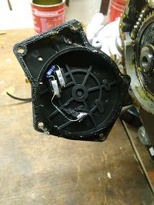
RAS, position sensor
RAS, magnets of position sensor
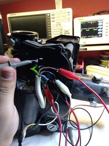
RAS, pulses of position sensor (reed switch)


It seems that the encoder is relative, so when the system starts, it is programmed for the zero position. When the system loses power, the rotator controller knows the last position, it stores the last position in a non-volatile memory. Also the system has two hard stops in the elevation axis, that limits the rotation between 0-180 deg. These switches immediately cut off the current to the elevation motor. There is no end stop in the azimuth axis.

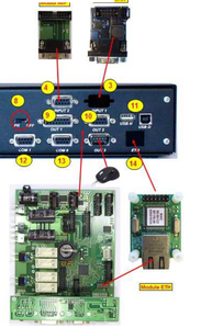
The default rotator controller is Rot2Prog, the motor driver consists of relays. The interface with the client is done with [Hamlib](https://hamlib.github.io/) via a USB. A note here: The cable is USB-A male to USB-A male, which is non-standard. The USB-Serial chip inside the Rot2Prog is normally powered via the USB port, and there are known issues with inrush current on Raspberry Pi units, resulting in the USB-Serial not operating. This can be resolved by modifying the Rot2Prog to power the FTDI chip from the onboard 5V regulator (which powers the main micro-controller) instead of the USB port.
Two rectifier bridges are used for protection of the board from the currents of the DC motors. The cost of Rot2Prog is ~250$.

The datasheet of RAS refers to a parameter called MTBF which is the mean time between failures. For the rotator controller is 15000 hours @ -5 to +40°C. For a system that is connected to the SatNOGS network, i.e.:
- in 1h, at least 2 observations of 15min each
- in 15000 hours, 30000 observations
- which means almost 2 years of operation
Station #232 has observed one relay failure (open circuit, thankfully) approximately every year of operation. The relays are readily available via most major electronics parts outlets, and are fairly easy to replace with a desoldering station. A suitable relay socket is also available to make relay changes easier.
Mechanical
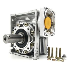
Both of the rotators consist of two stages of worm gear boxes. The second stage (the output) take all the load. In this system, the brake mechanism is the two stage worm gear box (big gear ratio and also the lead angle of worm gear). The cost for RAS with Rot2Prog controller is ~1200$, for BIG-RAS with Rot2Prog controller is ~1600$.
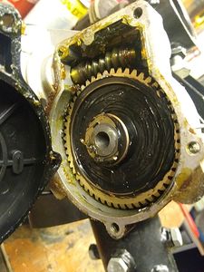
RAS, First stage of worm gear
RAS, Second (output) stage of worm gear

Alternative Rotator Controllers
A list of available digital controllers:
- RT-21 Azimuth/Elevation, Green Heron Engineering LLC, 889$. This has a nice feature: "Allows different Azimuth and Elevation rotators from any manufacturer provided they both use either AC or DC motors. (Example: We can configure the Azimuth to use an OR-2800 and the Elevation to use a DC motor linear actuator. OR, the Azimuth to use a T2X, and the Elevation to use a Yaesu G-550)"
- MD-01/02 HR, which is a high resolution edition rotator controller, with resolution of 0.1875 deg. Instead of using reed switches in the first stage of the worm gear box, it uses a hall effect sensor. Again, the motor driver consist of electromechanical switches, as shown in the picture on page 3 of the datasheet. This controller also supports soft-start functionality (PWM control), but only when the power supply is higher than 20V, according to this post.
The cost of this controller (only) is calculated:
- RAS/HR, RAS rotator and MD-02/HR controller is ~[1435E](http://www.rfhamdesign.com/products/spid-hr-antenna-rotators/ras-hr-az--el-rotor/index.php)
- only the RAS rotator costs ~900E (an estimation)
so the cost of MD-02/HR is ~500E.
RT-21 Azimuth/Elevation, Green Heron Engineering LLC
Rotator Controller, MD-01/02 HR


SPX rotators
Electronics & Mechanical
A series of AZ/EL rotators:
All of these rotators seem to be based on the same first stage worm gear box as the RAS. The second stage looks like this and changed according to the maximum output load (and maximum break torque). From all the data-sheets, it seems that the motor needs 12-18V@3-20A or 20-24V@3-20A (max current depends on load or rotator controller, e.g. PWM control). All of these rotators use the same controllers as RAS/BIG-RAS. The motors are DC (it seems that they are the same as RAS/BIG-RAS). For position sensor, a reed switch for the standard version and a hall effect sensor for high resolution version are used.
There are no end-stops to this rotator in either azimuth or elevation, with the rotation limits entirely controlled in software, which can enable 720 degrees of continuous azimuth rotation, and up to 180 degrees of elevation if the users cable and antenna mounting setup supports it. Most SPX-based systems only use 90 degrees of elevation movement, but 'flip' mode (like the Yaesu G-5500) is theoretically possible.
In this system, the brake system is the double worm gear. In the specification, the rotation range is AZ/EL:360/180deg - the same as the RAS. The available rotator controllers are the same as the SPID rotators (Rot2Prog, and MD-01/02).
A SPX-02 has been operating on station #232 for approximately 2 years, running in fairly light duty. The only failure in the rotator noted was a snapped first-stage worm-drive, which appears to be a manufacturing defect, and was replaced by the manufacturer for free. The brushed motors produce some EMI on both 2m and 70cm when moving, which can be mitigated using ferrites clamped over the control cables near the motor.
SPX, second stage of worm gear
SPX-02 rotator, station 232

