Adjusting the SatNOGS Client
Contents
Introduction
(This page is a port of DL4PD's excellent post to the SatNOGS forum.)
Prerequisites / dependencies
This page assumes:
- you've read all the Getting Started page, as well as the pages linked under "Build" and "Operate" on the Main Page
- you've already made your first observations and have some waterfalls in the Network
- you've installed install gqrx on your local computer.
Frequency Offset Calibration
Some cheaper SDRs may have a significant frequency offset, due to the use of poor quality reference crystal oscillators. This can result in observations which may be un-decodable. If you see observations that have signals that appear to be 'off to one side', then you should perform some of the steps below to determine your offset.
Automatic adjustment via kalibrate-rtl
As a more comfortable way to get the ppm of your SDR the tool kal from https://github.com/viraptor/kalibrate-rtl can be used. At the moment you probably have to get and build it by yourself.
Note: This is only going to work if GSM is still in existence in your country. If (like Australia), your country has moved on from the 1980s and deprecated GSM, you will need to use another option (scroll down).
When using the pre-built image for the Raspberry Pi, you have to install the following dependencies:
$ sudo apt-get install libtool pkg-config libfftw3-dev librtlsdr-dev automake m4
Then you can build and install it with
$ ./bootstrap
$ CXXFLAGS='-W -Wall -O3' ./configure
$ make
$ sudo make install
For usage, see available parameters:
$ kal -h
kalibrate v0.4.1-rtl, Copyright (c) 2010, Joshua Lackey
modified for use with rtl-sdr devices, Copyright (c) 2012, Steve Markgraf
Usage:
	GSM Base Station Scan:
		kal <-s band indicator> [options]

	Clock Offset Calculation:
		kal <-f frequency | -c channel> [options]

Where options are:
	-s	band to scan (GSM850, GSM-R, GSM900, EGSM, DCS, PCS)
	-f	frequency of nearby GSM base station
	-c	channel of nearby GSM base station
	-b	band indicator (GSM850, GSM-R, GSM900, EGSM, DCS, PCS)
	-g	gain in dB
	-d	rtl-sdr device index
	-e	initial frequency error in ppm
	-E	manual frequency offset in hz
	-v	verbose
	-D	enable debug messages
	-h	help
choose an appropriate band for scanning:
$ kal -s GSM900
Found 1 device(s):
  0:  Generic RTL2832U OEM

Using device 0: Generic RTL2832U OEM
Found Elonics E4000 tuner
Exact sample rate is: 270833.002142 Hz
kal: Scanning for GSM-900 base stations.
GSM-900:
    chan:   33 (941.6MHz - 155Hz)    power: 4877018.31
    chan:   41 (943.2MHz - 208Hz)    power: 2265226.87
    chan:   43 (943.6MHz - 133Hz)    power: 1287992.91
    chan:   55 (946.0MHz - 179Hz)    power: 1041611.46
    chan:   57 (946.4MHz - 252Hz)    power: 1405188.40
    chan:   66 (948.2MHz -  13Hz)    power: 5027059.56
    chan:   79 (950.8MHz - 111Hz)    power: 1088677.82
    chan:   84 (951.8MHz - 231Hz)    power:  945912.38
    chan:   86 (952.2MHz - 212Hz)    power: 2314696.93
    chan:  116 (958.2MHz - 180Hz)    power:  862935.90
choose a strong channel:
$ kal -c 33
Found 1 device(s):
  0:  Generic RTL2832U OEM

Using device 0: Generic RTL2832U OEM
Found Elonics E4000 tuner
Exact sample rate is: 270833.002142 Hz
kal: Calculating clock frequency offset.
Using GSM-900 channel 33 (941.6MHz)
Tuned to 941.600000MHz (reported tuner error: 0Hz)
average		[min, max]	(range, stddev)
- 206Hz		[-293, -89]	(204, 56.913998)
overruns: 0
not found: 0
average absolute error: 0.219 ppm
Now enter the measured ppm in satnogs-setup and you're done. The value should be entered without decimals, for example -1.
Automatic Adjustment using LTE Signals
If you are living in a country where GSM is no longer present, but LTE is available (in a frequency range supported by your receiver), then you can determine your SDR's PPM offset by following this guide: https://gist.github.com/darksidelemm/b517e6a9b821c50c170f1b9b7d65b824
Manual Adjustment using GQRX
If you cannot calibrate against GSM or LTE towers, but you have a nearby amateur radio beacon or transmitter at a reasonably well-known frequency, you can use this to obtain at least a coarse PPM correction.
NOTE: This section needs to be updated to follow the same process as is used in `Setting The Gain`, as rtl_tcp may not be available on the latest SatNOGS RPI images, and will not work if any other SDR type is in use.
SSH to your SatNOGS Pi with your well-known user account; by default, this is the user "pi". After successful authorization you will see a prompt like this:
 Linux satnogs190-dev 4.9.59-v7+ #1047 SMP Sun Oct 29 12:19:23 GMT 2017 armv7l

 The programs included with the Debian GNU/Linux system are free software;
 the exact distribution terms for each program are described in the
 individual files in /usr/share/doc/*/copyright.

 Debian GNU/Linux comes with ABSOLUTELY NO WARRANTY, to the extent
 permitted by applicable law.
 Last login: Fri Jan 12 07:34:11 2018 from 192.168.10.35
 pd@satnogs190-dev:~ $
You will now need to temporarily stop the satnogs-client, using the command:
$ sudo systemctl stop satnogs-client
Now go ahead and start the "RTL SDR spectrum server":
$ rtl_tcp -a 0.0.0.0
If everything is fine, you will get an output like this:
 Found 1 device(s):
   0:  Generic, RTL2832U, SN: 77771111153705700

 Using device 0: Generic RTL2832U
 Found Rafael Micro R820T tuner
 [R82XX] PLL not locked!
 Tuned to 100000000 Hz.
 listening...

Use the device argument 'rtl_tcp=0.0.0.0:1234' in OsmoSDR (gr-osmosdr) source to receive samples in GRC and control rtl_tcp parameters (frequency, gain, ...). No further output will be generated until you connect to this server. Hitting C-c will stop it and the command line appears.
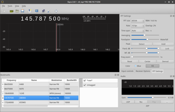
Now go ahead and start gqrx:
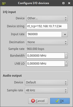
You will have to go to the setup menu, either by clicking on the "harde" symbol, or navigating through the menu item called "File -> I/O Devices"
Click on "Device" and chose "RTL-SDR Spectrum Server" Edit "Device string" to match your Pi's IP address, Port defaults to 1234, which is the same as the default setting for your server you just started on the Pi. Set "Input Rate" to something network friendly - we do not need the whole spectrum the RTL SDR is able to convert. 1,8 MSPS (1800000) should be OK Depending on this setting your network will get very busy. Using wireless LAN is not recommended. Every sample has a data size of 16 bits, so the previous setting of 1,8MSPS/s results in a network load of 28,8 MBit/s:
1,8 MSPS * 16 bit/s = 28,8 MBit/s
"Audio Output -> Device" and "-> Sample rate" should be set by default,
values on average soundcards would be something like "Default, 48 kHz"
Close the dialogue by clicking "OK"
Your RTL-SDR spectrum server on the Pi should now show up a connection from
your computer running gqrx.
 client accepted!
 set gain mode 1
 set agc mode 0
 set direct sampling 0
 Disabled direct sampling mode
 set offset tuning 0
 set sample rate 960000
 ll+, now 1
 ll+, now 2
 set freq correction 42
 set freq 144500000
 set gain mode 0
 set agc mode 1
 set gain 0
 set freq 145814000
 ll-, now 0
 ll+, now 1
 ll+, now 2
 ll+, now 3
 ll+, now 4
 ll+, now 5
 ll+, now 6
 ll+, now 7
 ll+, now 8
 ll+, now 9
 ll+, now 10
 ll+, now 11
 ll+, now 12
 ll+, now 13
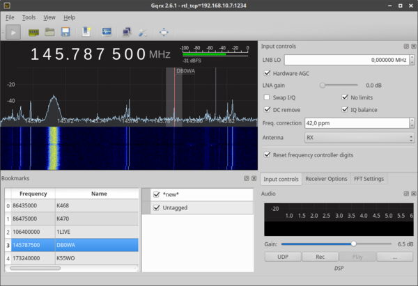
The only thing left now is to "Start DSP" - from the menu item "File", by hitting C-d or simply clicking the Play-Button.
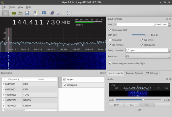
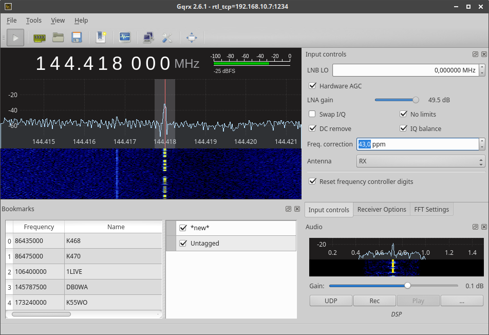
Go for a known local HAM radio repeater or a CW beacon transmitter and set your demodulator accordingly. Narrow Band FM or CW is best to discover ppm error offset, which is the frequency offset in parts per million (ppm) which is always there with standard RTL-SDR dongles. For SDRs without a Temperature Compensated Crystal Oscillator ('TCXO') this value may be temperature dependent. Enter the known frequency of your chosen transmitter (NFM repeater or CW beacon). I have chosen a very known CW beacon just some km away from my home: ON4VHF on 144.718000 MHz. Walk through the tab called "Receiver options" and change the settings to fit the beacon: "Filter width Normal", "Filter shape Normal", "Mode CW-L", "AGC Medium". Set Squelch to something low, so you can hear noise from your speakers. Maybe you have to Adjust the audio "Gain" to something like "0.0 dB". You can adjust this to fit your needs to hear noise. With ppm error, which is default, set to 0.0 ppm, one can just guess where your receiver is listening. Anyway, just set it to 144.718000 MHz and try to find your beacon. You can see the result for my RTL SDR dongle down here:
Now got to the tab called "Input controls" and find an input field called "Freq. correction". By default this should show "0,0 ppm". Set frequency back to your beacons transmit frequency. After this you have to increase the Freq. correction value as long until you can hear the beacon. Now zoom into the panorama by locating your mouse pointer in the range where the frequency values are printed below the panorama, just above the waterfall. Try to fit the Freq. correction value as good as possible, that your receivers red indication line is just in the middle of the transmitters bandwidth.
Now write down the evaluated ppm correction value and exit gqrx as well as the RTL SDR spectrum server. In the command line now available start satnogs-setup:
$ sudo satnogs-setup
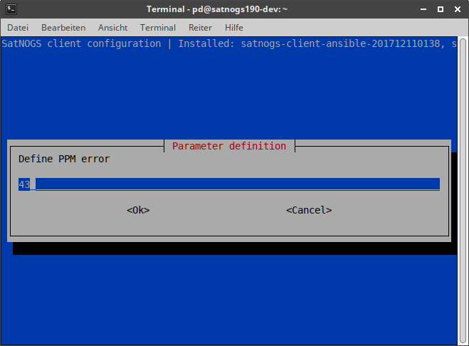
Navigate to "Advanced -> SATNOGS_PPM_ERROR" and enter the new value.
Exit the satnogs-setup with "Back", then "Apply Configuration" (this might take a while) and "Back".
You are done with frequency offset correction.
adjustment using observations
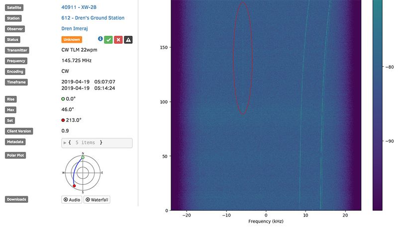
Another way of adjusting the frequency offset is by making an observation of a satellite that transmits CW. Once the observation is complete, the CW signal from the satellite should look like a straight line at 0Hz on the observation waterfall. If there's a frequency offset, the signal will be off-center. The image below shows observation details for a CW transmitter on VHF. Since the frequency offset is not yet adjusted, the CW signal is present between the -10kHz and 0Hz markers.
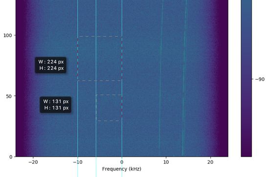
In order to compute the frequency offset, the waterfall image can be downloaded and opened with graphics editor like GIMP. After opening the waterfall image, vertical markers are placed on the -10kHz tick, the 0Hz tick and on the CW signal. Once the markers are placed, measure the width in pixels between the -10kHz tick and 0Hz tick, as well as the width between the CW signal and the 0Hz tick. The image below shows an example of the placed markers and the widths to be measured:
Let’s call the width between the -10kHz and 0Hz markers widthTickTo0, and the width between the CW and 0Hz markers widthCWto0. From the example image above, we get the values widthTickTo0 = 224 and widthCWto0 = 131. To compute the frequency offset, we compute the ratio between those widths and multiply by the frequency tick value as follows:
frequencyOffset = -10,000Hz * widthCWto0 / widthTickTo0
In the case of the example above:
frequencyOffset = -10,000Hz * widthCWto0 / widthTickTo0 = -10,000Hz * 131 / 224 = -5,848Hz
To compute the offset in PPM, divide the frequency offset in Hz by the transmitter frequency in MHz. In the case of the example above:
ppmOffset = frequencyOffset / transmitterFrequency = -5,848Hz / 145.725MHz = -40 PPM
The correction entered in satnogs-setup must have the opposite sign of that in the calculation, since we will be shifting the frequency in the opposite direction, making the SATNOGS_PPM_ERROR value:
SATNOGS_PPM_ERROR = 40
Note that if the CW signal is on the left side of the 0Hz marker, the PPM value is positive, otherwise, the PPM value is negative.
Enhancements
Waterfall Color improvements
By default the SatNOGS client will adjust the waterfall colour ranges to best display the received signal.
If desired, this auto-ranging can be disabled by running sudo satnogs-setup, and navigating to Advanced -> Waterfall. From here the auto-ranging can be turned off, and the minimum and maximum waterfall colour-scale levels can be set.
